Garrattfan's Modelrailroading Pages

NBDS 118-119
Chassis build up

 |
 |
 |
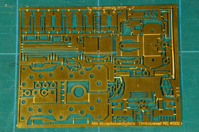
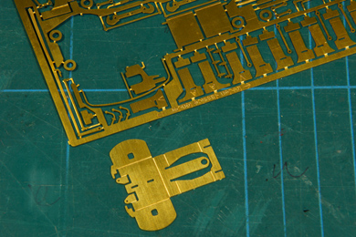
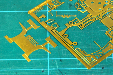
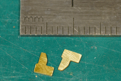
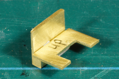
It was a bit of a search but this is the part that will be the pony truck of the leading axle. Note that the manual contains a map of all etched parts on page 37. This makes it easier to locate these in the etch (I should have looked).
I make folding easy with a steel ruler over the etch and razor blade underneath to bend the part over. So far I never had need of a fancy thing as an etch bending tool or so. |
 |
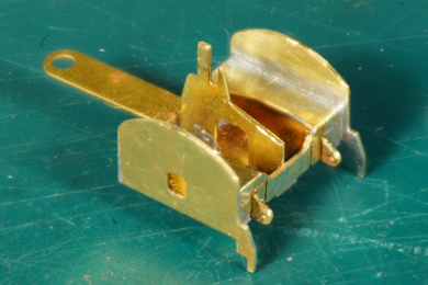 |
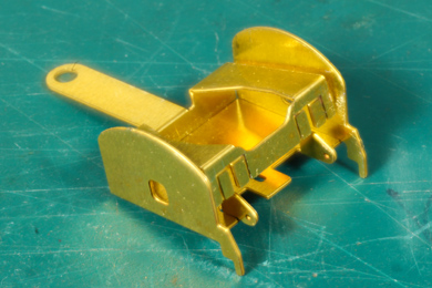
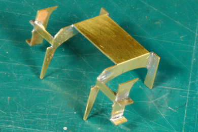
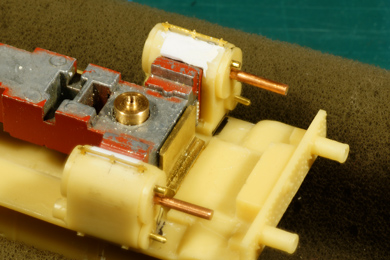
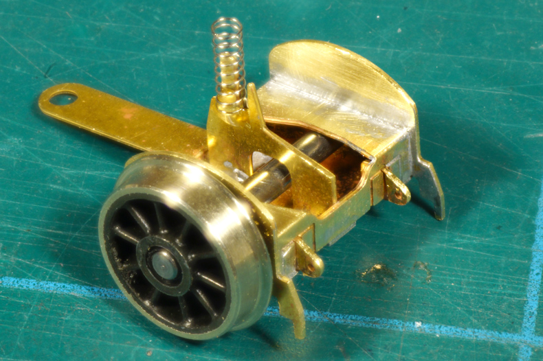
| The truck is folded and soldered. Soldering is a bit fiddly because it is a small part with lots of joins which can open up when another join is soldered. But it can be done. In the middle a "spike" is added. | |
The spike holds a spring which is held in place with a drop of epoxy. The axle holes are reamed until they can take the 2 mm axle. |
|
 |
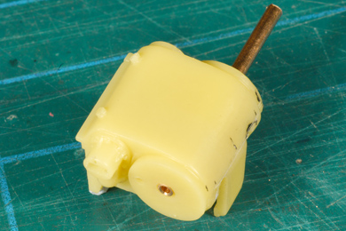
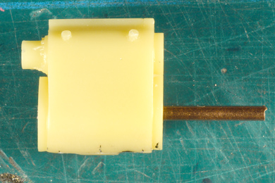
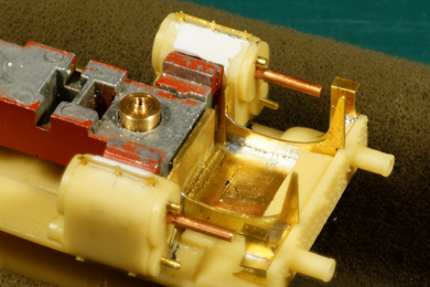
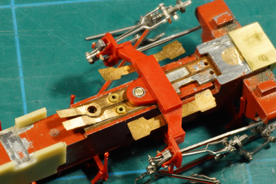
To attach the pony truck the manual recommends taking a plastic part from the original locomotive, adapting it with styrene tube and making a hole to take up a bolt. Here I deviated from the instructions. I appreciate the reuse of available parts, which may be an acceptable solution for the beginning modeller. I found the manual's construction too flimsy though, so out came the lathe. I turned a brass rod to fit in the frame, with an extra rim to hold the pony truck and a hole which was tapped with M1.4 thread. |
 |
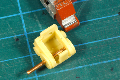
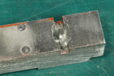
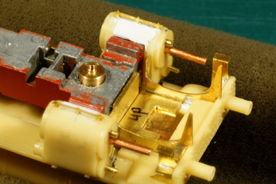
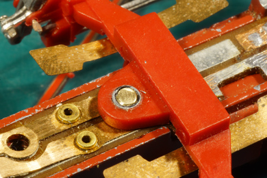
The brass rod can move up and down until the pony truck bar sits level. After some practising I added a bit of expoxy glue and set it to its final position. |
 |
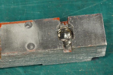
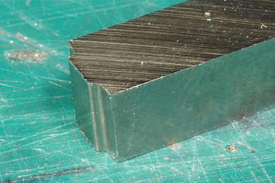
After the glue had set the top end was milled flush with the frame. |
 |
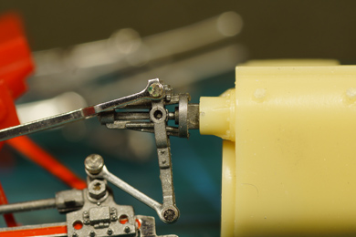
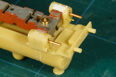
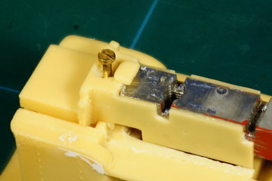
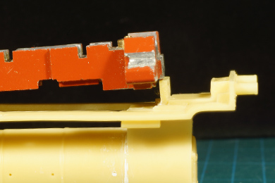
Attention turned to the cylinders. The manual recommends inserting brass rods in the front cover without mentioning the rear cover. At the rear though a big hole is staring at you. It is much wider than the piston rod that needs to go in. Sloppiness in the drive gear will be the result.
|
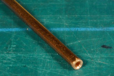 |
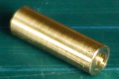
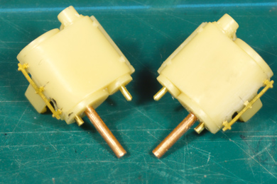
So once again I deviated from the manual. I happened to have a piece of brass pipe of the correct diameter and as a stroke of luck the inside diameter was wide enough to take the piston rod pretty accurately. I sawed two pieces of 22 mm length, the 9 mm the piston sleeve should extend ahead of the cylinder plus the width of the cylinder including both covers. I filled one end with a scrap of brass rod, soldered it in place and filed it down so the piston slide to close it at the front end. I chamfered the open rear end.
|
 |
 |
 |
This pipe was fed all the way through the cylinder and glued in both the rear and the front cover. Now I have ensured that
The setback is that the piston pipe did not clear the cylinder support on the frame,so I milled it out a little to obtain the necessary clearance. |
 |
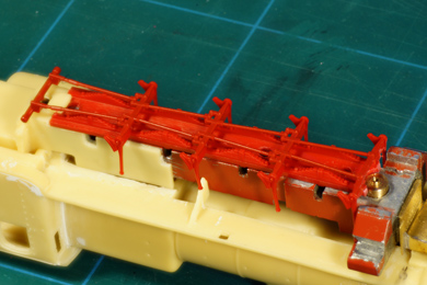
Other details are added |
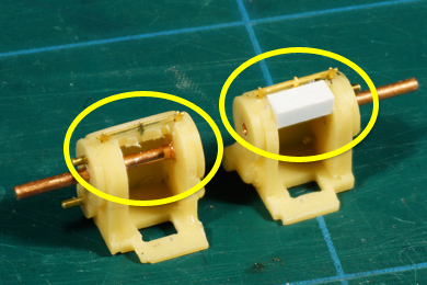 |
During fitting and removing one bottom clip broke off. Resin is prone to breakage and the manual already warned for this. As the cylinders without the clip will fit anyway I removed the bottom clip from the other cylinder as well. I filled the gap with a piece of styrene, filed to shape in situ. |
 |
The top end hole on the rear needed a little deepening to take up the valve gear.
|
 |
 |
| The frame front end was taken out of the etch fret as well as the minute steps that will be added onto the front ladders. | |
 |
Folded and soldered. No more to say than to be cautious as it is a vulnerable piece of brass art. |
 |
 |
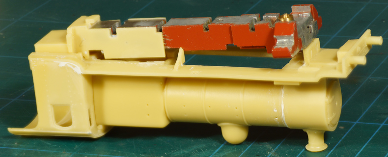
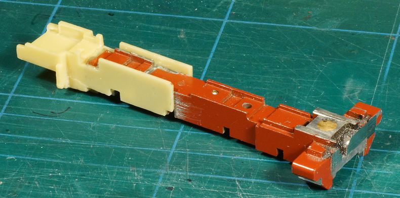
Another deviation from the manual. On the original locomotive the first and the fifth axle were provided with a spring. When sawing of the fifth axle the rear spring was lost. I milled a new receptacle for this spring around the fourth axle. So once again this loco has two sprung axles. |
|
 |
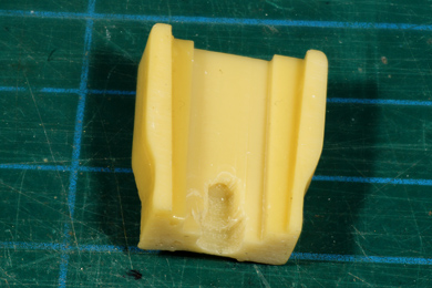
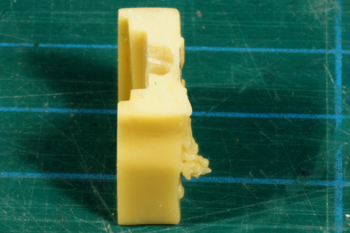
I cleaned up the running board. The vertical resin ridge of 2 mm thick should be kept in place. The manual says there should be an eccentric notch on the wall, but in my case there was an air bubble instead. No notch, no nottin'. The notch was intended to retain the front end of the frame. Not being there meant I needed to find a solution for that. I did not feel too unhappy about that as resin is fragile and a simple notch would have been susceptible to breakage anyway. So the think tank revved up. |
|
At this stage it is wise to build up the superstructure to the stage where the running board is well supported by the driver's cab and the boiler. |
|
The frame would not fit frame despite all sizes being okay. |
|
Was it the rear end to be amended ... |
... or the front end? |
In the end I milled down the front end |
|
But while fitting the superstructure I found the cylinders to be out of line. The frame had to move a little to the back. Well, I had to find a solution for the front attachment of the frame anyway. |
|
 |
 |
| I removed the resin ridge to provide space | |
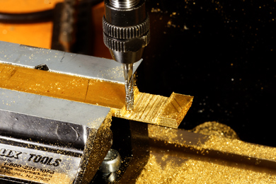 |
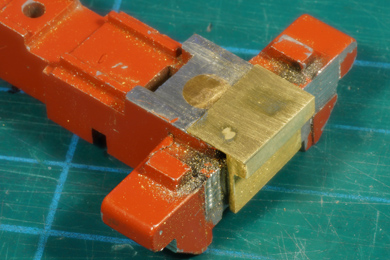
I milled a clamp from solid brass ... |
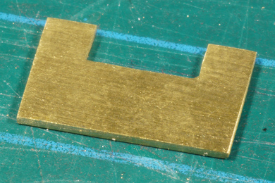 |
... and a catch from 0.75 mm brass sheet. |
 |
Clamp and catch should work like this. |
 |
 |
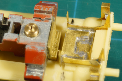
| First the clamp is glued to the front of the frame. | The frame front end is temporarily placed, |
 |
The catch is first tack-soldered, the frame front end is taken out of the superstructure and finally the catch is firmly soldered to the frame. For now the front end assembly is left loose.
|
 |
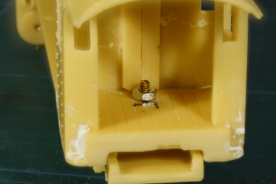 |
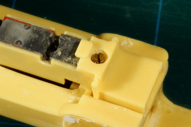
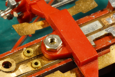
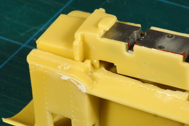
Making the rear end connection. On the rear end of the frame the resin extension has a dimple indicating where a hole should be drilled to accommodate the rear end bolt. Drill this dimple with a 2.0 mm drill. Drilling resin, by the way, can easily done by hand. The material cuts quite easily. I prefer hand-drilling over machined drilling as it gives you a good control for what is happening. The rear end hole should line up perfectly with the hole already provided in the floor of the driver's cab. To receive and fix the bolt a nut is needed in the driver's cab. A bit of epoxy secures it in place. The thread can be protected from intruding glue by a bit of grease.
|
|
 |
 |
In a late stage of the build I replaced the nut. It came loose after a few trial assemblies and disassemblies. So I deemd the nut solution too unreliable. I turned a collared bush with 2.0 mm thread and glued that bush in a somewhat widened hole in the floor of the cab |
|
 |
 |
| To hide this nut (and later the bush) and bolt from sight a hollow is made in the boiler backhead. | |
 |
Measuring the height of the running board when the locomotive is put on its wheels, I found that the model leaned a bit forward. So I made a small shim of 0.35 mm brass sheet to lift the front side of the locomotive.
|
 |
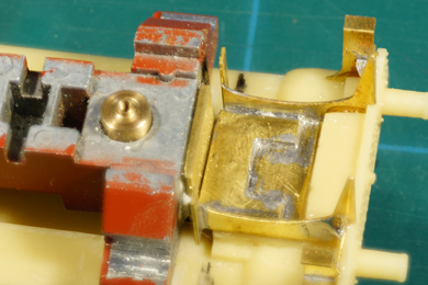 |
Once every is right, the completed frame front end is glued to the underside of the superstructure, after which the frame slides into place as demonstrated in the two photos above ... |
|
 |
... and secured by the rear end bolt. |
 |
The bottom plate which secures the wheel sets is made to fit. I needed to scrape away a millimetre or so at the rear end to make it fit. |
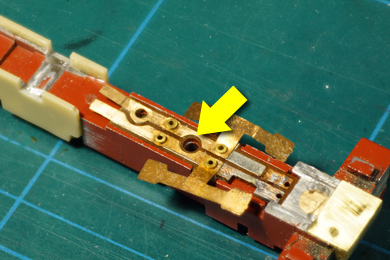 |
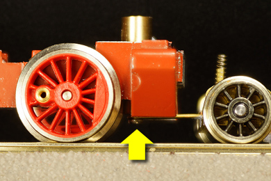
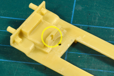
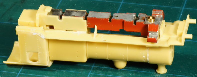
Next issue to solve is how to connect the bottom plate cum brake gear to the frame. The manual is conspicuously silent about this. On the original locomotive a long brass rod with a short threaded end ran through the frame (yellow arrow) into the boiler where it was bolted into. As a consequence my frame has no thread. Using a standard bolt and nut would mean this nut would be very visible because is exactly in sight under the boiler. |
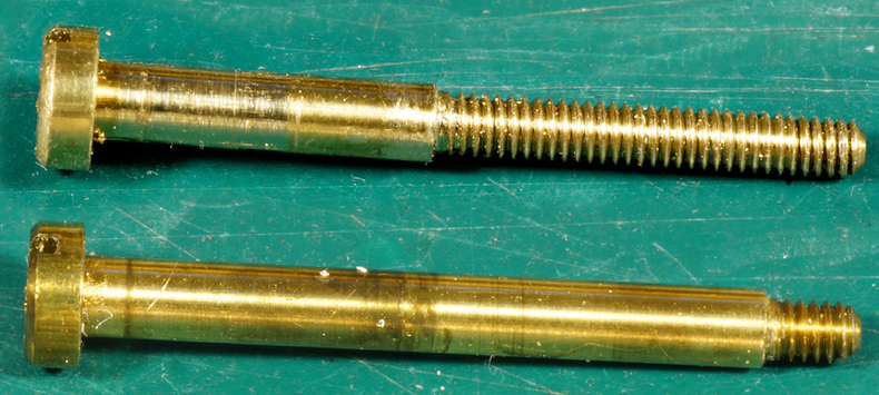 |
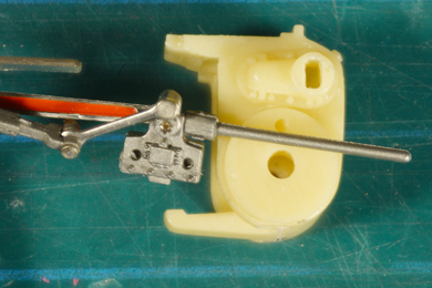
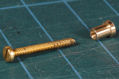
I hate throwing away perfectly good things so I took the original bolt through the frame (bottom) and extended its thread (top). I also turned a hexagonal M2 nut to a round shape. |
 |
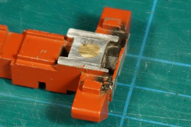
I inserted the rounded M2 nut into the motion bracket and secured it with epoxy. I shortened the brass bolt to the desired length. |
 |
 |
It will hardly be visible after painting. For comparison I laid a normal M2 nut on the bracket to show what a difference it makes. |
|
 |
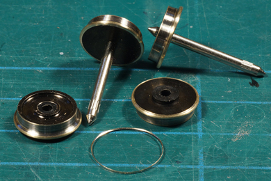
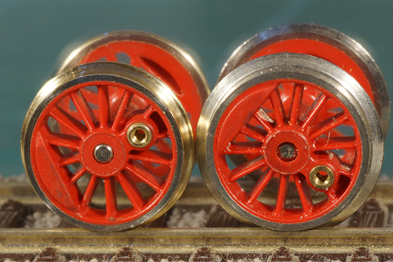
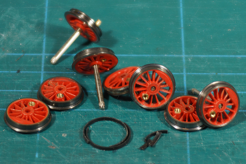
The frame is now nearly complete. The only job remaining is turning the flanges of the driver wheel sets to RP25 norms. I bought an RP25 tool from Fohrmann. No cheapy, but excellent quality. Its is set under angle of 3 degrees in the lathe and side 1 is used to cut the flange down just until the front touches the wheel's tread and then side 2 is used to round off the back side. Once you get the hang of it, it pretty straight forward. I did not buy the rather expensive wheel holding fixture holder tool. I want to think of a way of turning the wheels without removing them from the axle,so without disturbing the quartering. |
 |
I first practised on the wheels of a few freight wagons, to get the hang of it |
And after some practising I felt confident enough to try my newly acquired skills on the one superfluous axle (remember this model is converted from an 0-10-0 to a 2-8-0 so I have one axle to spare). |
|
And then soon followed the other four axles. After turning they where blackened. The traction tires succumbed to the process, so I ordered a few spares. |
|
I used a simple card quartering tool to requarter the wheelsets. I described making and using the tool on a separate tooling page. |
|
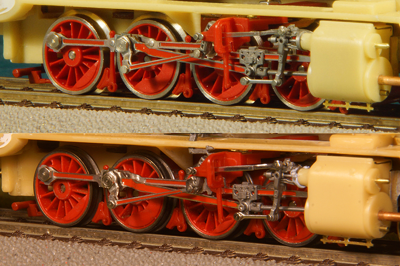
A "before and after" comparison |
|


Sign my
GuestBook